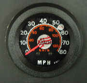
Need a speedometer for your GMC we have the solution. Our speedometer
works on almost any bus with cam style air brakes, positive or negative ground, 12
or 24 volt, no problem. This spedo will work in your GMC 4104, 4106, 4905, Fishbowl, Old,
Look, Flex, MCI, Eagle, Prevost, and just about anything else. We can install it, or, if
you want to install it yourself we'll send you the whole kit and give you phone support if
you get stuck!
Still not sure you want to tackle this project? I've added the
installation instructions so you can determine if this is a project for you.
1. Mount meter into instrument panel in standard S.A.E. 3 3/8 inch hole, using U
clamp and wiring nut furnished with meter head.
2. Connect light assembly by attaching white wire to good ground connection
point
and black wire to instrument light dimming switch.
3. Red and white meter wires should be connected as follows:
White wire to negative point and red wire to positive point.
If vehicle has negative ground power system, white wire should be grounded to
vehicle ground and red wire connected to hot buss. Power should be supplied to meter at
all times (even when vehicle is not used for several months), rather than to ignition
switch.
If vehicle has positive ground system, red wire should be connected to vehicle
frame and white wire to hot buss. Power should be supplied to meter at all times.
4. Dress pickup cable through fire wall and along cable routing path to front
wheel. (Some units are supplied with cable connector not soldered to cable. This is done
to allow cable to pass through smaller holes). After cable is located, connector should be
soldered to cable leads. Use rosin solder only. Never use acid core solder or acid
flux.
5. Locate pickup at front wheel leaving enough cable slack to allow
front wheels to steer from full left to full right and for front springs to flex without
putting strain on cable.
6. Position pickup so that magnet end comes approximately 1/8 inch from 4
"bumps" or "holes" in turning member such as brake drum flange. If
brake drum flange is smooth and lacks irregularities, the pickup will sense 4 holes
drilled into flange.
Holes should be at least ¼ inch in diameter and ¼ inch deep. Materials must be
attracted by a magnet (cast iron or steel), better results can be obtained by tapping 4
holes in flange and fastening 4 cap screws into holes. The pickup should be positioned so
that it allows bolt heads to pass freely with about 1/8 inch clearance. If meter fails to
register at low speeds, move pickup closer. If meter reads double speed or jumps to double
speed at high road speeds, move pickup further away.
If bolts or holes are equally spaced, the meter reads smoothly over the entire
dial. If brake drum is predrilled with two holes on each side of drum, a slight flicker
will be noticed at low speeds (below 20mph).